Senior Design Project:
Ultimate Line-Level Converter
Senior Capstone Design Project, completed my final year of undergraduate studies at the University of Miami. The device is an innovative all-in-one stereo converter for consumer and professional line-level specifications, and is designed to be a convenient and higher quality replacement for converter cables. The device accepts any cable type as an input or output, and it will maximize signal quality in every configuration. Completed for the "Capstone" course (MMI410), a class offered by the University of Miami.
Project Overview


This device is an all-in-one solution for all line-level applications. Simply put, it converts between the two line level specifications, consumer and professional.
Consumer Professional
-10dBv nominal level +4dBu nominal level
unbalanced signal balanced signal
RCA, 3.5mm aux XLR, TRS
Intended Use
The device's main intended use is to be a higher-quality replacement for conversion cables, and for connecting various electronic devices to PA systems speakers. This is perfect for lower budget gigs, as lot of the time you don't know what kind of inputs venue's PA system supports. This is also true if you're a live sound engineer, where often times you don't know what outputs a performer has on their system.
Normally, this means means you would have to carry a lot of converter cables with you to be prepared, which takes up valuable backpack space and adds weight if you're on-the-go. Instead, you can simply carry this device with you to solve the issue; since the device features every cable type commonly used for line-level audio, there will never be a need for conversion cables. Simply carry 2 XLR cables, 2 TRS cables, 2 RCA cables, and a 3.5mm aux cable, and you can plug any device with a stereo output into any system with the best possible audio quality in every configuration.
The device can take any cable type as an input or an output: XLR, TRS, RCA, and 3.5mm aux. When converting from consumer to professional, it will balance the signal and boost it by 11.78dB, the exact level difference between -10dBv and +4dBu. When converting from professional to consumer, the "hot" and "cold" signal are added together to provide a stronger, lower noise unbalanced output. In this configuration the signal is also attenuated by -11.78dB instead, ensuring device compatibility. In either case, you get the maximum benefits of a balanced signal regardless of the arrangement.
The direction of conversion can be changed easily with the switch on the right-hand side of the PCB. In addition, the device allows for the device to have multiple outputs at once, and allows the device to be used passively to convert XLR to/from TRS, and RCA to/from 3.5mm aux if needed. This is made possible by the connectors being connected in parallel.
This is the first prototype. Theoretically, the form factor and cost of components can be cut down significantly, and can also feature a proper housing to hold the electronics safely.
PCB Design - KiCad

4 layer board
Planes (from top to bottom): Signal, V+, V-, Ground
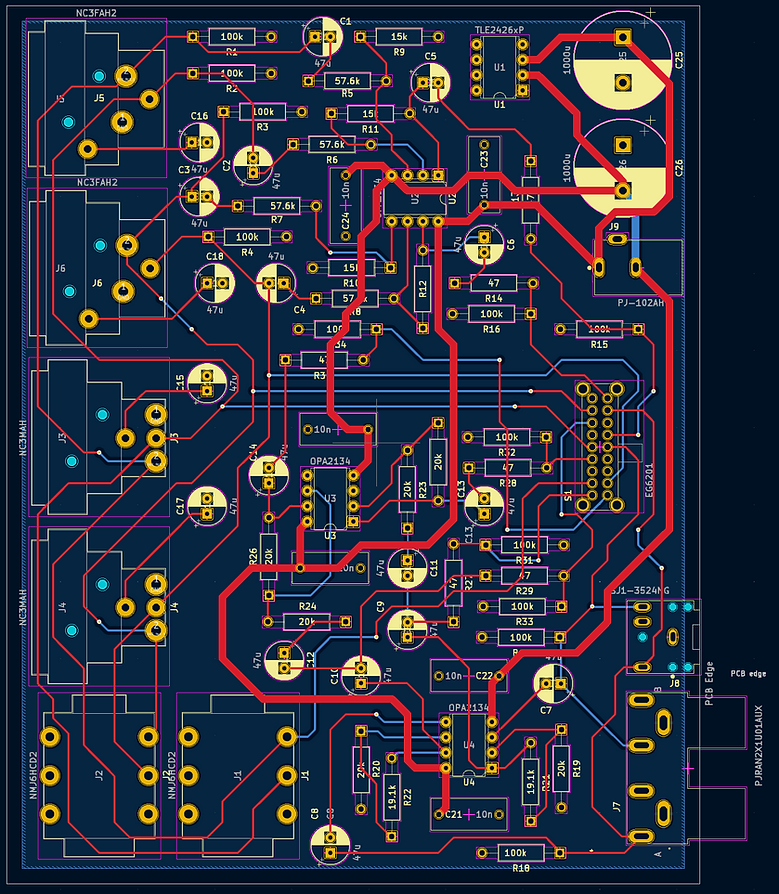
2 layer board
Schematic - KiCad

Simulations - PSPICE
PSPICE software was used to simulate individual segments of the circuit in order to find appropriate resistance and capacitance values. Values were chosen to achieve the 11.78dB difference between consumer and professional specifications, all while maintaining a flat frequency response in the audible hearing range and blocking unwanted DC signal.
Balanced to Unbalanced: Differential Amplifier


Differential amplifier and its resulting frequency response. Simulated gain of -11.691dB.
Unbalanced to Balanced: Non-Inverting & Inverting Amplifier


Balancing circuit and its resulting frequency response. Simulated gain of 11.839dB.

Breadboarding and Testing
Breadboarding a simplified mono version of the device. The top circuit is the non-inverting and inverting amplifiers, and bottom circuit is the differential amplifier.
Oscilloscope: Balanced to Unbalanced

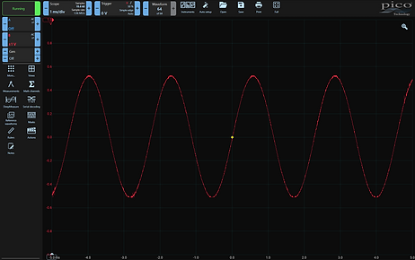
Input: Balanced Hot - 1V Peak
Output: Unbalanced - 526mV Peak
Hot - Cold = 2V Peak
Measured Gain: -11.60dB
Theoretical: -11.69dB
Oscilloscope: Unbalanced to Balanced


Input: Unbalanced - 1V Peak
Output: Balanced Hot - 1.94V Peak
Hot - Cold = 3.88V Peak
Measured Gain: 11.78dB
Theoretical: 11.84dB
Balancing Audio: Hot and Cold Signal

"Hot" and "Cold" signal recorded separately into Ableton. The phase flip can clearly be seen between the two signals.
PCB Fabrication from JLCPCB
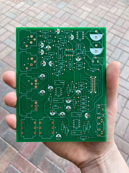

2 layer board: 5.7 x 4.5 inches


4 layer board: 5.7 x 4.15 inches
Components Selection
Integrated circuits - Texas Insruments OPA2134
-
Dual Op-Amp, Dip 8
-
Known as one of the best audio op-amps for the price
"Rail Splitter" - Texas Instruments TLE2426
-
Provides very stable virtual ground at half of the supplied voltage
-
with 12 volt supply, 6 volts becomes "ground" for the entire circuit
-
Provides negative voltage for op-amps
-
Resistors - Vishay Dale CMF55 Series
-
Very high-quality metal film resistors
-
Great for audio applications
Coupling capacitors - Rubycon YXJ Series
-
Regarded as one of the best aluminum electrolytic capacitors
-
Higher capacitance values
Power capacitors - Rubycon ZLJ Series
-
Good for power applications
Op-amp bypass capacitors - Panasonic ECW Series
-
Very high-quality film capacitors
-
Great for audio applications


Summary of Results and Future Improvements
Once the build was completed, the device worked as intended; when converting from a consumer-specification connector to professional, the input was balanced to a "hot" and "cold" signal, with an overall gain of 11.78dB. When converting from professional to consumer, the hot and cold signal were consolidated for an unbalanced output, and attenuated by -11.60dB.
However, there was a slight yet noticeable distortion when dealing with higher amplitude outputs. From previous testing, it seemed to be an impedance mismatching or power issue; the signal started to distort at different amplitudes depending on the input impedance of the connected device. This may be due to the fact that I used a "rail splitter" (TLE2426) to provide a positive and negative voltage, which is only capable of providing a small amount of current. A better approach would be to bias each op-amp with a simple resistor divider, so power throttling wouldn't be an issue. This would definitely need to be fixed in future prototypes before it is considered as a viable working product.
In addition, I realized that even though the ±12dB difference followed the line-level specifications, it was a very drastic change—almost annoyingly so. I think practically, having a gain/attenuation closer to ±6dB would be more appropriate. This would also keep the hot, cold, and unbalanced signals at the same amplitude, which could be possibly taken advantage of in future prototypes.